Our services - Engineering Technologies

Main menu:
Our services
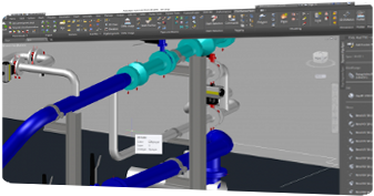
Making or technicals drawings is our goal, morever in the piping process.
Pipe constructions uses a large number of methods and the process of realization, often complex. Due to their numbers and weights induced, it needs a clear scheme in order to calculate the metallic support. For this reason a technical drawing for every pipe must be realized.


The first technical drawing is the ISO. The symbols represent fittings, valves and flanges. Because, ISO”s are not drawn to scale, dimensions are required to specify exact lengths of piping runs. ISO scheme are used to determine through calculation using coordinate en elevations using North-South and East-West coordinates.
This mentions process piping, sizes, flow directors, interconnection reference, flush and bypass line, mechanical equipment process control instrumentation and designation including valves and their identification , control imput and outputs, sensors, computer control system etc…
